When I started it back up the inductor blower started up properly and something was rattling around inside the flue pipe. The gas ignitor glowed red for a moment and then the whole thing gave up. It retried 2 or 3 times before giving up, starting the blower and flashing me an error code on the control board.
I should have realized at this point that since the igniter was lighting up that all the interlocks and sensors were working properly. It is unlikely that it would heat the ignitor and just not turn on the gas if a sensor was not seeing that the inducer fan was running or something, unfortunately I was still listening to that noise in the flue pipe and was distracted by that. I thought perhaps something had made a nest in the pipe so I disconnected it to have a look. I found dead bees...
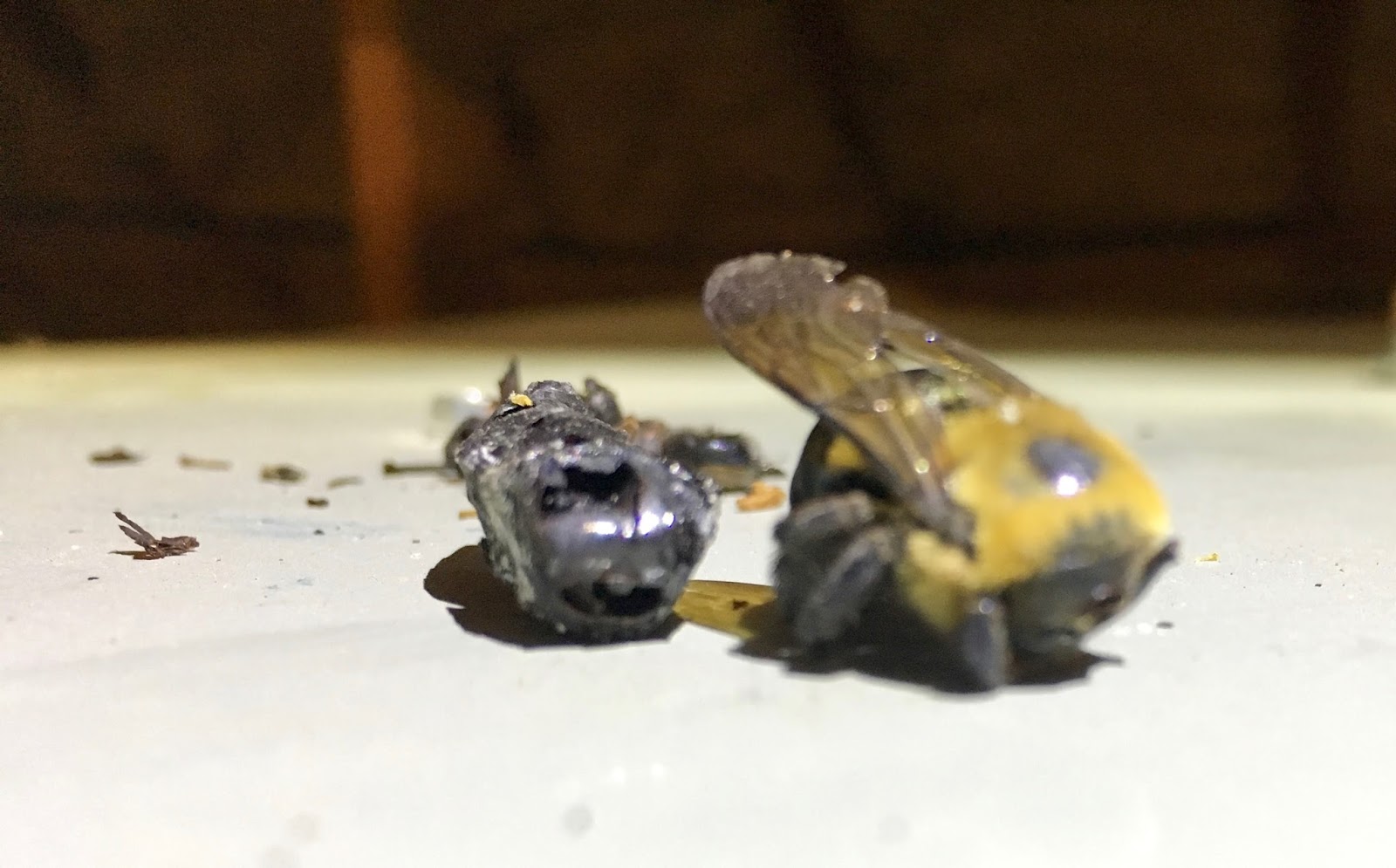
Not many and they were all dead thank goodness, cooked or blackened by the heat. Continuing to ignore the fact that the ignitor was working I decided that the flue had to be blocked by a hive even though I could hear no buzzing anywhere and no live bees came out of the furnace or the flue. I still wasted the next half an hour taking apart the inductor fan and heat exchanger to see if the sensor pipe was clogged with hundreds of cooked bees or something. This involved messing with some rather friable high temperature fiberglass gaskets that would be nasty if you got it on you or inhaled it. You probably don’t want to remove those parts because of that.
It turns out that the bees were not the problem at all and had just distracted me from what should have been the obvious conclusion that the gas valve wasn’t turning on. Now that I had eliminated the impossible bees I could move on to actual debugging. Keep in mind that your furnace has many ways to kill you, exposed line voltage, high pressure gas lines, quickly spinning sharp things that may start up when your finger is in a place to get sucked into them, a gas ignitor that heats to red hot and fire to name just a few. Then if you don’t get it back together right or if you don’t wire the interlocks back on properly it won’t protect you from itself later and may burn your house down or kill you and your family from CO poisoning some night months or years from now. Even if it doesn’t kill you it might eat itself and replacing a cracked heat exchanger because the temp cutout wasn’t working is very expensive and not something you can do yourself. I make it a point to actually look at things before I call a repair man because many times it turns out to be something I can fix and save myself the call. But thats my choice and you should probably make a different choice for safety’s sake.

Putting the meter on the gas valve showed no power to the solenoid so it wasn’t just that the gas valve was bad, the board wasn’t sending it any power. At this point if you’re screwing around inside your stuff you probably want to turn off the circuit breaker so that you don’t hit the cutoff switch while you’re holding the board and electrocute yourself.

Tracing the wires from the gas valve to the large plug at the bottom of the picture above and then to the relay right next to it. In my case there were 2 sets of red and blue wires going into this plug, so don’t rely on color to tell you which wire was which. I gave that relay a short sharp wrap with my screwdriver and reconnected it. For 2 cycles it sent power to the gas valve! Success we found the problem! I can replace a relay on a single sided PC board no problem. Unfortunately it was an 18v coil and I didn’t have any of those laying around to just drop in. I considered replacing it with a solid state relay for a moment, but the ones I have on hand don’t have an input voltage range that goes that high, and they weren’t the same form factor so I would have had to make a mess of it by running wires to an external relay. Not an ideal solution.
Then it occurred to me that when the other furnace failed for a similar reason a couple of years ago I had actually saved the control board that they swapped out at great expense. One of the relays on this board was bad too, but there are 4 identical relays on the board so I should be able to find one of them that was still good!

You’ll see 4 empty positions on this board where I desoldered the relays. The boards are conformal coated on the back and have lots of surface mount components on the back side. You can’t desolder through the coating so I used a dremel with a small wire brush to scrape off the coating and get to the pads.

Being very careful not to damage the surface mount parts or scrape off the tiny traces that were very close to the relay pins! That was less important on the old board than it would be when working on the new board, but this was an opportunity to practice. It turns out that the brush also removed most of the solder as well turning it to very fine dust that covered the board and went into the air. This board is probably older than lead free solder so I decided to do the rest of the pads outside so that I wouldn’t breath in any lead dust or get it all over my work bench. With most of the solder scraped off the pins they desoldered very easily. It’s interesting in the picture to see the surface mount transistor and snubber diode that controls the relay and protects the CPU from induced back current are right under the relay itself there.
I was a little concerned about making sure which of the old relays was bad, but that turned out to be easy. Not just an intermittent or faulty connection one of them had a coil that was open circuit so filtering out the bad one was easy. That left me with 3 good ones. One to repair this board and 2 to save for future spares.
Now it was time to remove the existing board from the furnace. You did turn off the circuit breaker before you did this right? I would also consider it vital to label all the wires you’re taking off, there are many connections and nothing is obviously labeled on the board other than the thermostat wires. Even the thermostat wires on my furnace didn’t match up color wise, the power lead wasn’t red, it was yellow. They had run the power to the thermostat through the float switch in the pan below the furnace and returned that with a different colored wire to those connections. So don’t just rely on your perfect eidetic memory to remember where all these connections go. Make labels and take pictures.

I was concerned about the yellow and red wire there going to the blower. They were both on a pad that was called “park” rather than going to a specifically named pin that I could label them. So I took pictures of that to get it right again later. It occurred to me later that “park” probably meant that they were not connected to anything and were just “parked” there ;) Looking on the back of the board did reveal that those wires are not actually connected. It’s a place to park extra leads from the blower motors so they aren’t flopping around in there shorting against other things or getting sucked into the blower. I believe they are for running the blower at different speeds and were not needed in my install. In the case of “parked” leads the order you connect them won’t matter. Everything else is important to get right or you’ll cook the board or burn your house down.

This is the existing board. You can see there is quite a bit of discoloration of the conformal coating around some of the surface mount components where they get quite hot. None of them have failed yet, so perhaps they are still within their spec. There is a lot of airflow in that part of the furnace since this board mounts inside the blower cabinet. These still get hot enough to discolor the coating, that doesn’t look good.
Since I had already dremeled off the coating over 4 other relays on the old board doing it one more time without damaging the surface mount connectors or board traces was easy. Since I knew the board was bad anyway if I had damaged them and couldn’t repair it I wouldn’t be any worse off than I already was except for wasting all this time.

The replacement relay has been soldered on! The conformal coating around the pads bubbled up and burned a bit during the soldering process but I was less worried about that then melting the solder on the adjacent surface mount components and having them migrate away. That didn’t happen when I was desoldering on the other board though and that takes much more time and heat than putting a new one back in. I think the coating would keep them in place even if you did overheat the board, at least to a point, but you’ll want to be careful not to do that.
Put the board back in and used my pictures and labels to reconnect all the terminals on the board and we have heat again! Nobody does board level repairs anymore but it can certainly be done depending on what the problem actually is. I have 2 more spares for when more relays fail on these now aging furnaces in the house. So far so good and however many more seasons of heat I can get out of these before they need to be replaced will save money.