Showing posts with label debugging. Show all posts

Friday, January 29, 2021

Instrument Cluster Board Level Repairs And The Evils of Lead Free Solder

 My wife drives a Ford C-Max “energie” plugin hybrid. It is an awesome little car that Ford no longer bothers to sell in the US because they failed to market it well enough and it became unprofitable for them to keep them around. Or it is possible that Americans really are only interested in double sized trucks and SUV’s and simply don’t want smaller cars at all. I don’t know but I suspect a combination of both problems exist. In any case I was in Chicago 4 months ago caring for my mom and I got a call from home saying that the dashboard on the car was completely blank. Had to manage remotely getting her a rental and getting the car fixed at the dealership. A couple of thousand dollars later we had a new instrument cluster as the old one was dead. It took weeks to get fixed as a new one had to be ordered with the proper odometer reading burned into it. 


This morning it did it again! Not even a full 4 months later! Car starts but the instrument cluster stays dark and eventually the touch screen/ radio comes up with a message that says “Vehicle Network Communication Error” and will not do anything else. Other interesting side effects are that the climate controls defaulted back to Celsius without being able to talk to the instrument cluster. 

Since there is no way to control most of the car and no way to know easily how fast you’re going the car is simply not safe to drive that way beyond just not having to have it towed to the dealership. 

The local Ford dealership said that since this was an electrical problem it required special attention from special people and they wouldn’t be able to even begin to work on it for 5 days! Don’t bother bringing it in before this coming Wednesday! And no willingness to tell me if this would be a warranted repair since they just did it. 

As I sat here fuming about how long we’d have to rent a car for as they ordered another new one for us I decided that since it was dead anyway I’d take it out and have a look at it. I’ve rarely regretted doing that and have often found that I could make a repair to something that would have cost a lot of money to replace unnecessarily. 

It turns out that it’s very easy to remove the instrument cluster from most Ford cars. There are lots of youtube videos about it but basically you pull the cowling that connects the rubbery sheet that covers the top of the adjustable steering column to the plastic under the cluster straight towards you and then that reveals the 2 7mm bolts that hold in the cluster. Make sure to adjust the steering wheel all the way down and forward or you can’t get it out. On this C-Max there are 2 clips that you need to force to let go directly behind it, but I have no idea if just yanking it straight out is the right thing to do for your model or not. It was the right thing for mine. Grab the cluster and pull it straight towards you until they let go. If you do it wrong or yours is held on differently though you might break something expensive so find a take apart video for your specific model before you start applying excessive force to anything.

There is a single connector on the back that you can reach around and find the pinch spot to easily remove it. You may want to put a towel over the cowling part or any other exposed plastics to keep from scratching them as you figure out how to get the cluster out from between the steering wheel and the dashboard. It is possible, but only just.


It actually look me longer to clear enough room on the desk to work on it than to get it out of the car ;) After carefully removing all the other plastic coverings you get to the point of having to remove the speedometer meter pointer. There is no D shaped or otherwise locking connection point for this. It is strictly a friction fit piece of plastic pushed down over the pin that comes up from the stepper motor that drives it. At this point it is recommended that you take a piece of tape, I used electrical that didn't seem to damage the plastics or paint or printed parts underneath it but go easy on it, and make that line up with exactly where the pointer is at it's sopping point. You'll notice it is a little below zero but if you get this wrong when you put it back together you'll be driving at a speed other than what you think you are. "I took the dash apart Officer and evidently did not get the pointer back on right" is not going to get you out of a speeding ticket. Put some tape on the underside lined up with it's stop point so that you get it back together right.

I used a "spudger" and very gently pried it up on both sides. The plastic these parts are made of feels like the lowest quality styrofoam and I believe they would break if you so much as looked at them wrong. If you don't have a proper spudger put some cloth or something to protect the black plastic background as you pry upwards or you will damage it and have to look at the light soaking through your scratches forever.

The next thing you have to remove to get to the board are the connections to the 2 screens on either side. I didn't capture a picture of this but I HATE these kind of board connectors. I've ruined many similar ones on Raspberry Pi camera connectors or others. In this specific one the connectors had a black plastic bar across the ribbon connector that you VERY GENTLY pried upwards to release the ribbon cable and then could slide the ribbon cable out. For me they worked very well but if you have any qualms about this sort of thing don't do it. You must remove them to safely work on the board though because once you take off the front plastics nothing else is holding them in place and any force or movement will be transferred to the connector which will either rip the cables or tear the connectors right off the board. It does not take much force to do that at all so really be seriously careful at this point. I would also make sure you don't confuse the left and right screens. I couldn't see any difference in looking at them but it seemed like a good idea not to put it back together backwards. They would certainly fit just fine backwards but who knows if they have different firmware or something.

And finally you'll have the nice board you can have a good look at!


It is, of course, almost entirely surface mount and there just isn't much you can do about that unless you're much more of a professional soldering god than I am. I put it under the inspection microscope and can see a lot of connections that looked a bit iffy to me. The first thing I did was to put some flux over the through hole pins that go to the connector on the opposite side of the board. You can see them as two rows of parallel pins in the picture aboe right in the middle of the board towards the top. I then carefully touched each one up with some nice antique leaded solder making sure not to over do it. I then searched the board for other such connections and found lots that looked like they were not particularly well done. I also touched up the larger connections in the several different power regulators on both sides of the board though I don't know if that or just the connector itself was what finally brought it back to life.

Many of the CPU connections looked quite badly done to me as well but I did not try to reflow any of them in the initial attempt to get this working as I was almost certain that if I touched them I'd make things worse and not better.

I re-attached the screens and the plastic case parts necessary to hold them and provide for the cable attachment point to the car and took it back to the garage and low and behold it lit up!


Took it back upstairs and re-affixed the speedometer indicator and the rest of the plastics and it kept working! 

This is almost certainly a failure to make proper connections while using lead free solder. The connections seem to become brittle and just break. I have assembled only 1 device with lead free solder, a wonderful clock kit and every 2 years I have to take it apart and resolder one of the LED displays with good old fashioned lead free solder as the original connections fail one after another. 

It should be possible to do such things properly with lead free solder, but it is my opinion that it requires slightly different design and probably different or better flux and other such things. The solder joints themselves look so horrible with lead free solder that I think it would be impossible to validate them with visual inspection the way you can with leaded solder. A cold leaded solder joint is obvious. The ones that failed with lead free solder look identically awful to me to the ones that are still working. 

In any case, if you have the skills you should take things apart and look at them before you pay someone many thousands of dollars to replace it. We may be putting less lead into the land fills but we're putting a lot more entire assemblies into them because of it. It seems there should be a solution that properly recycles leaded boards while still letting you use what is so obviously a superior way of making things that should last for more than a few years.

I'm off to cancel the appointment at the Ford dealership for next week and to complain to someone who has no idea what the parts are made of and who won't know who to contact to complain at corporate that their instrument cluster boards are patently defective because they have not carried lead free solder construction techniques over into their new lead free board designs. I know it's pointless but I'm still going to complain to them...

Friday, January 5, 2018

High Sierra hangs your main thread when the screen is asleep!

Thanks to Ben Bird of bensoftware and SecuritySpy fame I was able to work around the problem in High Sierra. If any Mac users are interested in really good DVR software I can whole heartedly recommend his Security Spy app. It works great with XTension and we even have an interface that will let you get motion data out of the program and assigned to units in XTension for taking other actions based on that.

The problem is evident in Mac OS version 10.13.2 and may actually have been introduced in the .2 update as I don’t recall having this problem immediately upon my updating to High Sierra but only more recently. I could be completely wrong about that though.

It turns out it has nothing to do with App Nap at all, I was barking up the wrong tree about that completely. It’s a rather nasty bug in some of Apple's screen drawing code. If you have an app that has an interface and it causes interface elements to update once the screen goes to sleep High Sierra will eventually just hang. Something causes a thread contention with the screen drawing. This might not be a big problem for most user apps as if the screen is asleep then you’re not using them. They will wake up along with the screen as soon as you touch the computer again. For an app that needs to keep doing things while you’re not there like XTension does this is tragic.

My first attempt at a fix was not successful. You can subscribe to events to tell you when the screen is put to sleep or woken up. In the event where the screen is going to sleep I hid all my open windows and in the event waking up the screen I showed them again. This was not enough to stop the thread contention issue. Possibly even drawing the menu is enough to cause the problem. I am not able to disable all the drawing in the app as far as I know. Though there are calls for windows to defer updates. There may be a Cocoa way to disable all screen drawing and I’ll have a look at that later. The pressure is off right now because I was able to get it working with a background helper app to check for the the main thread hanging in the app.

Ben had suggested a thread that pinged or otherwise checked on the regular spinning of the apps main thread. I tried this, but since I’m working in Xojo I’m limited to cooperative threads. If you block the main thread in a Xojo app you also block any other threads. Which is important to know if you’re working with threads and using semaphores to manage access to resources between the threads and the main thread. So I wasn’t very confident that the pinging thread would be effective since I expected that thread to get hung as well. That was indeed the case, the second thread stopped as well and so was never able to wake the screen.

The solution, hopefully temporary until Apple fixes this, was to create a separate terminal app to do the waking of the screen. Since command line apps have no GUI they aren’t affected by the problem. The background app just listens for a single character to arrive via STDIN. If it doesn’t get one from the main app at least every 5 seconds it makes a call to the Power Manager to assert a User Activity. Using the MBS plugins for Xojo this is easy, but I suspect it could fairly easily be done with a declare or external method call to the right library.  To wake the screen I just did this:


Dim userActivityID as integer

Dim err As Integer = IOPMAssertionMBS.DeclareUserActivity( "waking screen for thread contention", IOPMAssertionMBS.kIOPMUserActiveLocal, userActivityID)
   
You’re supposed to keep that userActivityID around and re-use it for any previous calls, so don’t just reset it to 0 each time you make this call. Though I’m not sure if thats really necessary.

The terminal app is copied into XTension’s resources folder during compilation and I’ve created an interactive shell class in XTension that is very simple. It just launches the app and starts a timer that sends a “P” to the shells stdin every second. Since timers fire on the main thread they are all silenced by the thread contention issue and so it stops sending that ping. 5 seconds later the screen wakes up and all starts working again. If I set the timing to much less than 5 seconds then I seem to get a lot of wakeups for slightly longer program operations like regular database saves and such. The 5 seconds seems a good compromise between having it hang all the time and just keeping the screen awake all the time.

Which is the other solution. You could just call that user activity constantly or tell your users to not let the screen go to sleep at all. Both things also “solve” the problem. Interestingly enough making the request to stop app nap and adding the flag for stopping idle sleeping of the screen did not solve the problem. So App Nap is not keeping the screen awake in those cases, or perhaps the screen saver is starting or something I don’t know, but just doing that did not solve the problem.

Thursday, November 17, 2016

A Distraction of Bees During A Furnace Control Board Repair

I woke up half an hour before my alarm the other morning thinking it was rather colder in the house than it should be. The furnace blower was running, but it was just blowing cold air. Thats rather frustrating. Two years ago I had to have the control board in another unit replaced and knew that this was likely going to be an expensive repair and they weren’t going to have the proper parts and would need to order them and I’d have to wait with no heat. After getting the kids to school I went up to have a look.

When I started it back up the inductor blower started up properly and something was rattling around inside the flue pipe. The gas ignitor glowed red for a moment and then the whole thing gave up. It retried 2 or 3 times before giving up, starting the blower and flashing me an error code on the control board.

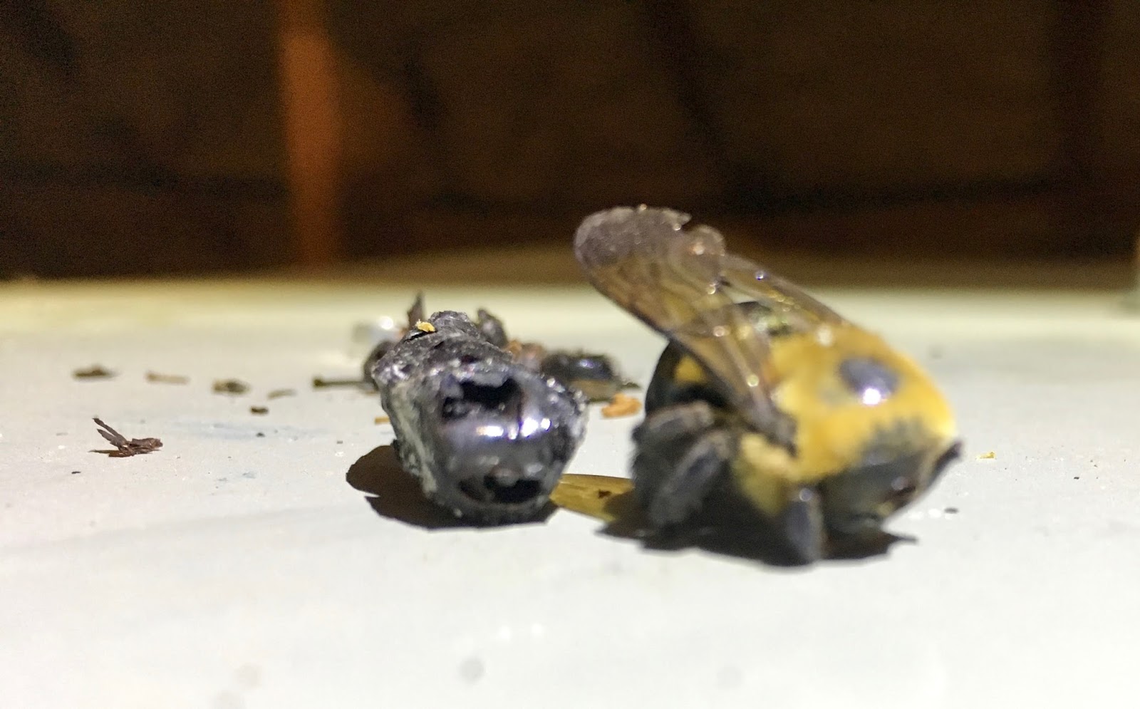
I should have realized at this point that since the igniter was lighting up that all the interlocks and sensors were working properly. It is unlikely that it would heat the ignitor and just not turn on the gas if a sensor was not seeing that the inducer fan was running or something, unfortunately I was still listening to that noise in the flue pipe and was distracted by that. I thought perhaps something had made a nest in the pipe so I disconnected it to have a look. I found dead bees...


Not many and they were all dead thank goodness, cooked or blackened by the heat. Continuing to ignore the fact that the ignitor was working I decided that the flue had to be blocked by a hive even though I could hear no buzzing anywhere and no live bees came out of the furnace or the flue. I still wasted the next half an hour taking apart the inductor fan and heat exchanger to see if the sensor pipe was clogged with hundreds of cooked bees or something. This involved messing with some rather friable high temperature fiberglass gaskets that would be nasty if you got it on you or inhaled it. You probably don’t want to remove those parts because of that.

It turns out that the bees were not the problem at all and had just distracted me from what should have been the obvious conclusion that the gas valve wasn’t turning on. Now that I had eliminated the impossible bees I could move on to actual debugging. Keep in mind that your furnace has many ways to kill you, exposed line voltage, high pressure gas lines, quickly spinning sharp things that may start up when your finger is in a place to get sucked into them, a gas ignitor that heats to red hot and fire to name just a few. Then if you don’t get it back together right or if you don’t wire the interlocks back on properly it won’t protect you from itself later and may burn your house down or kill you and your family from CO poisoning some night months or years from now. Even if it doesn’t kill you it might eat itself and replacing a cracked heat exchanger because the temp cutout wasn’t working is very expensive and not something you can do yourself. I make it a point to actually look at things before I call a repair man because many times it turns out to be something I can fix and save myself the call. But thats my choice and you should probably make a different choice for safety’s sake.


Putting the meter on the gas valve showed no power to the solenoid so it wasn’t just that the gas valve was bad, the board wasn’t sending it any power. At this point if you’re screwing around inside your stuff you probably want to turn off the circuit breaker so that you don’t hit the cutoff switch while you’re holding the board and electrocute yourself.


Tracing the wires from the gas valve to the large plug at the bottom of the picture above and then to the relay right next to it. In my case there were 2 sets of red and blue wires going into this plug, so don’t rely on color to tell you which wire was which. I gave that relay a short sharp wrap with my screwdriver and reconnected it. For 2 cycles it sent power to the gas valve! Success we found the problem! I can replace a relay on a single sided PC board no problem. Unfortunately it was an 18v coil and I didn’t have any of those laying around to just drop in. I considered replacing it with a solid state relay for a moment, but the ones I have on hand don’t have an input voltage range that goes that high, and they weren’t the same form factor so I would  have had to make a mess of it by running wires to an external relay. Not an ideal solution.

Then it occurred to me that when the other furnace failed for a similar reason a couple of years ago I had actually saved the control board that they swapped out at great expense. One of the relays on this board was bad too, but there are 4 identical relays on the board so I should be able to find one of them that was still good!

You’ll see 4 empty positions on this board where I desoldered the relays. The boards are conformal coated on the back and have lots of surface mount components on the back side. You can’t desolder through the coating so I used a dremel with a small wire brush to scrape off the coating and get to the pads.

Being very careful not to damage the surface mount parts or scrape off the tiny traces that were very close to the relay pins! That was less important on the old board than it would be when working on the new board, but this was an opportunity to practice. It turns out that the brush also removed most of the solder as well turning it to very fine dust that covered the board and went into the air. This board is probably older than lead free solder so I decided to do the rest of the pads outside so that I wouldn’t breath in any lead dust or get it all over my work bench. With most of the solder scraped off the pins they desoldered very easily. It’s interesting in the picture to see the surface mount transistor and snubber diode that controls the relay and protects the CPU from induced back current are right under the relay itself there.

I was a little concerned about making sure which of the old relays was bad, but that turned out to be easy. Not just an intermittent or faulty connection one of them had a coil that was open circuit so filtering out the bad one was easy. That left me with 3 good ones. One to repair this board and 2 to save for future spares.

Now it was time to remove the existing board from the furnace. You did turn off the circuit breaker before you did this right? I would also consider it vital to label all the wires you’re taking off, there are many connections and nothing is obviously labeled on the board other than the thermostat wires. Even the thermostat wires on my furnace didn’t match up color wise, the power lead wasn’t red, it was yellow. They had run the power to the thermostat through the float switch in the pan below the furnace and returned that with a different colored wire to those connections. So don’t just rely on your perfect eidetic memory to remember where all these connections go. Make labels and take pictures.


I was concerned about the yellow and red wire there going to the blower. They were both on a pad that was called “park” rather than going to a specifically named pin that I could label them. So I took pictures of that to get it right again later. It occurred to me later that “park” probably meant that they were not connected to anything and were just “parked” there ;) Looking on the back of the board did reveal that those wires are not actually connected. It’s a place to park extra leads from the blower motors so they aren’t flopping around in there shorting against other things or getting sucked into the blower. I believe they are for running the blower at different speeds and were not needed in my install. In the case of “parked” leads the order you connect them won’t matter. Everything else is important to get right or you’ll cook the board or burn your house down.


This is the existing board. You can see there is quite a bit of discoloration of the conformal coating around some of the surface mount components where they get quite hot. None of them have failed yet, so perhaps they are still within their spec. There is a lot of airflow in that part of the furnace since this board mounts inside the blower cabinet. These still get hot enough to discolor the coating, that doesn’t look good. 

Since I had already dremeled off the coating over 4 other relays on the old board doing it one more time without damaging the surface mount connectors or board traces was easy. Since I knew the board was bad anyway if I had damaged them and couldn’t repair it I wouldn’t be any worse off than I already was except for wasting all this time.


The replacement relay has been soldered on! The conformal coating around the pads bubbled up and burned a bit during the soldering process but I was less worried about that then melting the solder on the adjacent surface mount components and having them migrate away. That didn’t happen when I was desoldering on the other board though and that takes much more time and heat than putting a new one back in. I think the coating would keep them in place even if you did overheat the board, at least to a point, but you’ll want to be careful not to do that.

Put the board back in and used my pictures and labels to reconnect all the terminals on the board and we have heat again! Nobody does board level repairs anymore but it can certainly be done depending on what the problem actually is. I have 2 more spares for when more relays fail on these now aging furnaces in the house. So far so good and however many more seasons of heat I can get out of these before they need to be replaced will save money.
.code { background:#f5f8fa; background-repeat:no-repeat; border: solid #5C7B90; border-width: 1px 1px 1px 20px; color: #000000; font: 13px 'Courier New', Courier, monospace; line-height: 16px; margin: 10px 0 10px 10px; max-height: 200px; min-height: 16px; overflow: auto; padding: 28px 10px 10px; width: 90%; } .code:hover { background-repeat:no-repeat; }